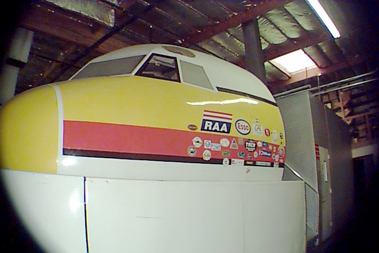
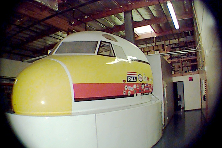
Here is another view of the exterior. The silver box behind the cab is where the navigation instructor's console is located.
Here is another view of the exterior. The silver box behind the
cab is where the navigation instructor's console is located.
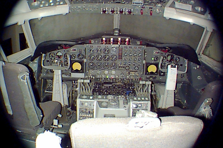
This is the interior of the Electra. The third seat at the bottom
of the picture is for the Flight Engineer.
Notice that instead of having a central throttle quadrant, both the
Captain and First Officer have their own set of throttles.
The throttles are designed to reverse the prop pitch when lifted and
pulled completely aft. This has the same effect as a
thrust reverser on a standard jet airliner.
This view shows one of the Flight Engineer panels on the upper right
and the upper portion of the central overhead panel.
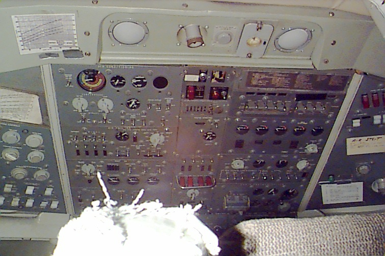
Here is a bit of a better view of the central overhead. Unfortunately
it's been far too long since I worked on this beast to be
able to accurately describe anything you see here. :)
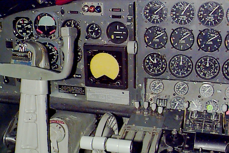
This is the Captain's side of the flight deck. The yellow display
is a Bendix weather radar display.
The gauges visible, from top to bottom are:
1. RPM
2. Turbine Inlet Temperature
I don't recall what the third is and the image is not clear enough
for me to puzzle it out based upon the scale.
If anyone can tell me what it is, I'd be happy to list it.
The four throttles are visible in the lower middle of the picture.
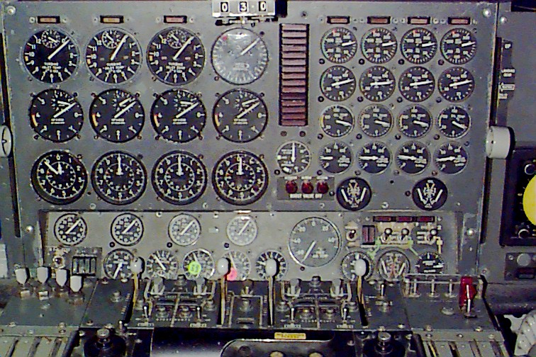
This is a much better picture of the engine gauges. Electra pilots
were VERY busy people. The center stack of red
indicators are various system warning and failure lights. The
gray knob to the far right is the landing gear handle.
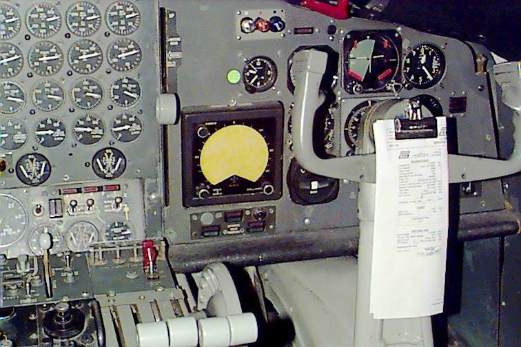
This is the First Officer's office. As you can see, it's a duplicate
of what is on the Captain's side. You can see the ADI or
Artificial Horizion and the Altimeter.
The silver, orange and blue lamp assembly is the Inner, Middle and
Outer marker lights. As the aircraft approaches these
navigation beacons, the light will blink with the morse code that's
being transmitted from each beacon. What PC flight
simulators never seem to simulate is the sound of approaching and leaving
the "cone" these beacons transmit. As the aircraft
approaches each beacon, the sound & illumination is very faint,
increasing with volume and brightness as the aircraft flies over
the area of highest signal strength, and then diminishing again as
the plane flies away from the respective beacon.
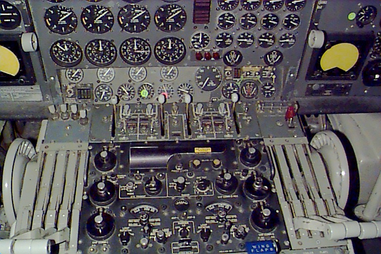
In this image, you can see the primary communications and navigation
radio panels. To the left of the FO's throttle quadrant,
you can see the top of the wing flap lever. You will note two
wheels on either side of the center console. These are the
manual trim wheels for the elevators. They're connected internally
by a splined shaft. These are used in the event that
the electric trim system that's activated by the switches on the pilot's
yoke fails.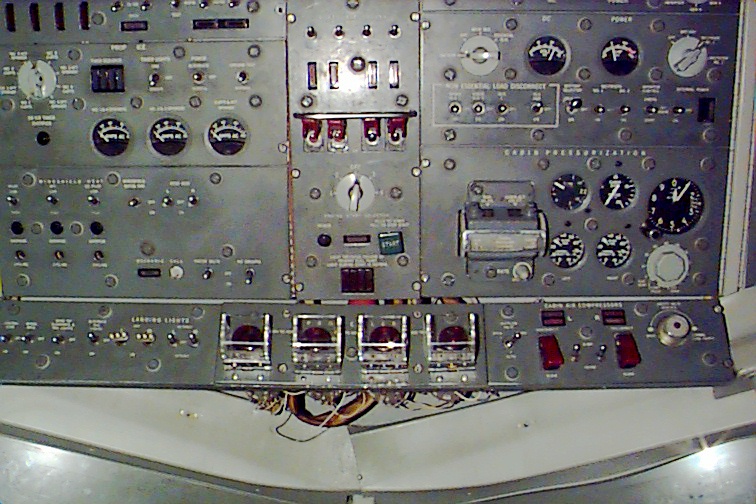
This is the lower portion of the central overhead console. In
the lower middle of the console are four plastic covered red
"slam buttons". These are used to force the connected propellor
to feather. This is typically done if there is some kind of
serious engine problem or an engine fire. For those that don't
know, "feathering" a prop adjusts each blade so that it's
parallel to the direction of flight, thus reducing drag.
This image is either part of the Instructor Station, or the Flight
Engineering station. I don't recall which.
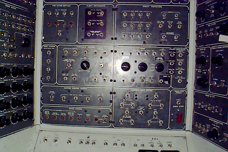
This image is of the Instructor Station. With this panel, a flight
instructor can create various in-flight situations, from an
instrument failure, to an engine fire or runaway propellor.
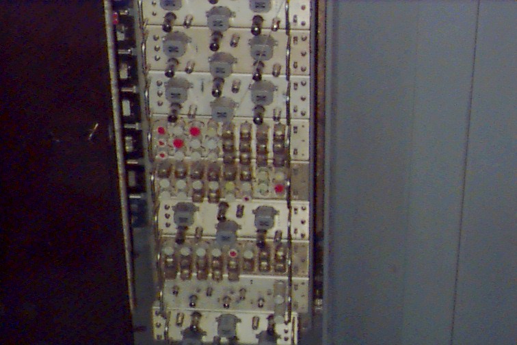
This is a picture of one of the dozens of racks that contain the hundreds
of tubes and relays that make up the computer that
drives the Electra simulator.
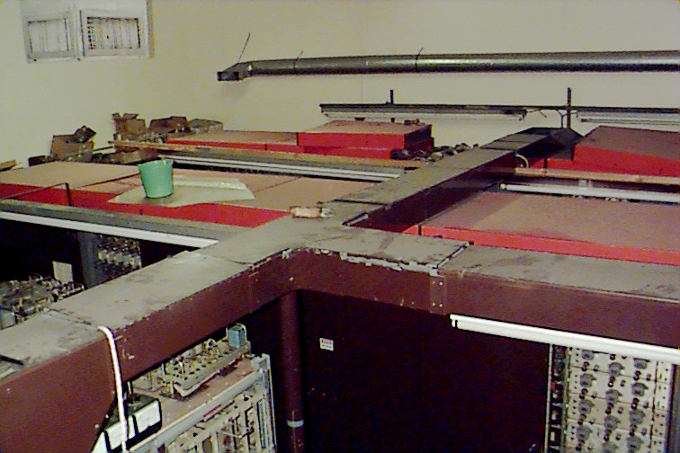
This picture was taken on the deck right behind the simulator cab.
Here you can see the three rows of cabinets that make
up the analog computer for the Electra. There are NO semiconductors
anywhere in this computer. It's entirely tube and relay.
Each line of cabinets is about 35 feet long. and contain dozens of
the rotate-out panel assemblies like that shown in the
previous image. Typically, this computer is turned off when not
in use due to the extreme heat it produces and the incredible
thirst for electricity it has. When a crew needs to use the simulator,
they MUST give at least 7 days advance notice.
The reason for this is that it takes 7 days of having the power on
for the whole computer to heat stabilize. Until the computer
is "heat-stable" it will not accurately simulate the Electra because
the components haven't had a chance to "normalize".
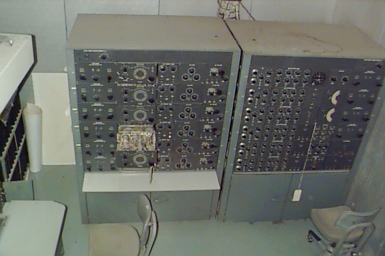
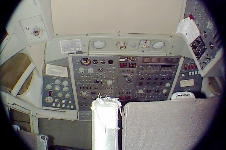
This is the instructor station that's located right behind the simulator
cab. These two cabinets control the radio navigation
beacons like VORs and NDBs, as well as the OMI marker beacon system.
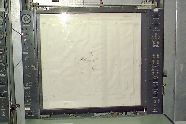
This is the navigation plotting board. This unit displays where
the aircraft is located at with respect to various radio markers
and "terrain". The indicator on the upper left hand side shows
the aircrafts current heading. This is typically used by the
instructor to verify the accuracy of the approaches flown by the students.
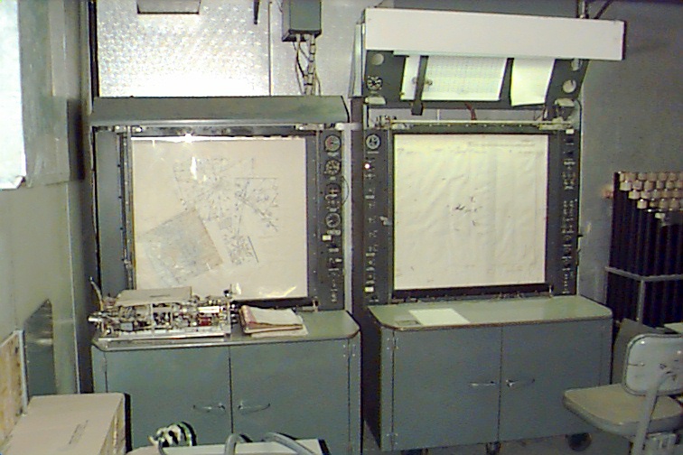
In this picture, you can see the mate to the above station. The
console on the left is what the instructor uses to set up each
training scenario. By utilizing the controls on this console as well
as the radio beacon controls shown in the prior image, he or
she can simulate any known IFR approach in the world.
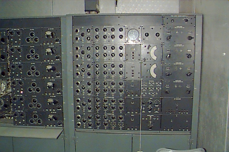
Here is a close-up of one of the radio beacon consoles.
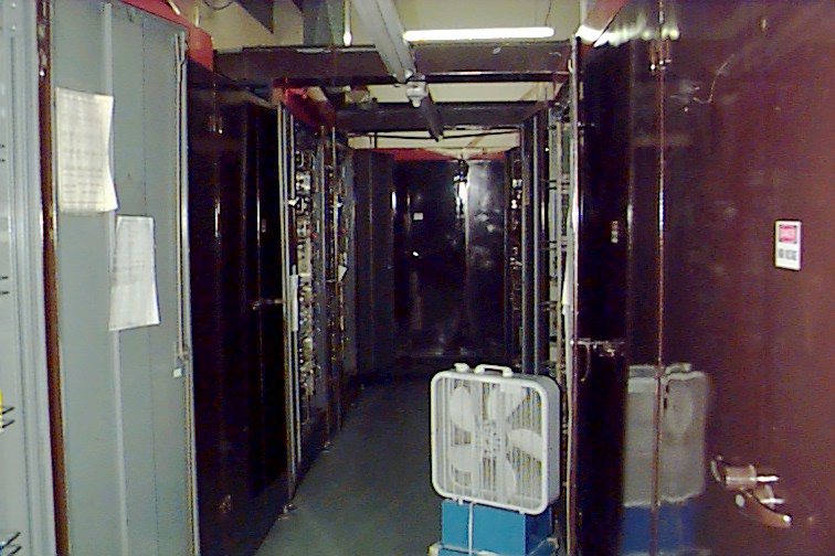
Here is a long shot down the far left row of consoles. As you
can see by the lack of blade-blur in the fan, the computer
is not turned on. :)
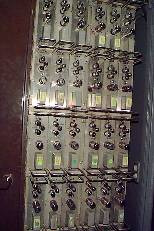
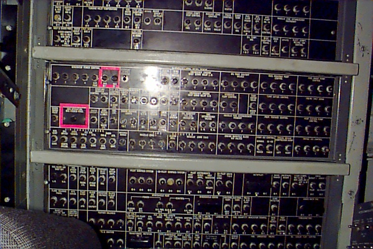
Here is a close-up shot of one of the rotate-out relay/tube racks.
Unfortunately, I don't recall what this particular
unit controlled.
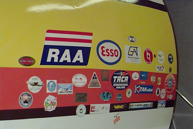
...and here we are back again looking at the side of the Lockheed Electra.
It's become sort of a tradition for each new crew to use the Electra
to bring along a decal that represents the airline or air
service that they fly for. Being the only Electra left, it's
kind of important. Most of the crews that use the Electra these days
come from South America. There are a few remaining cargo carriers
down there that use the Electra for long haul transport.
The Electra is also used (or at least as of 1995) by the Brazilian
Air Force. They use this simulator for navigation and
procedures training.
On a final note, the United States Navy still flies the Lockheed Electra.
The Navy calls it the P-3 Orion and it's used for anti-
submarine warfare. In the P-3 configuration it carries many sonobuoys
for detecting hostile submarines and a load of
torpedoes for killing them.
I hope you've enjoyed this tour of the Lockheed Electra IFR and Procedures
Trainer.
Gene Buckle
April 24th, 2000.