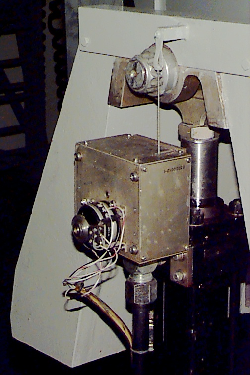
This is closeup of the positioner feedback pot. There is one just like it on the right actuator frame and the center actuator frame in the rear middle.


This is closeup of the positioner feedback pot. There is one
just like it on the right actuator frame and the center actuator frame
in the rear middle.
The wire coming out of the top is just a plastic coated wire rope.
It winds around a spring driven wheel that's in
turn mounted to the 10 turn precision potentiometer mounted on the
side of the box. This is how the computer
knows what position the actuator is currently in. Much fun can
be had if you walk by the sim while a flightcrew
is using it, and "strumming" the line. The result is the simulator
cab will "kneel" in the side you pull the line on.
Problem is, the video then no longer matches the slant of the flight
deck and the crew begins to turn green if you
persist in fiddling with it. :)

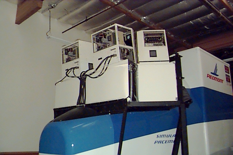
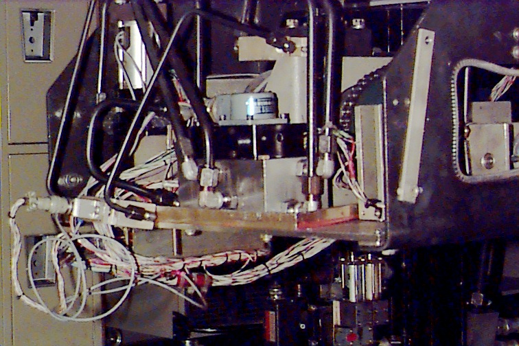
This is a picture of the center actuator, located in the rear of the
simulator cab, dead center.
The C/M 737-200 simulator is known as a 3-Axis system. It only
has three motion points (left, right and "heave" provided by the actuator
shown here).
Since this simulator was manufactured in 1967, it only operates now
due to a grandfather clause in the FAA regulations. The simulator
only provides nighttime levels of exterior illumination and the systems
response is
within the 300ms reaction time as specified by the Class A certification
guidelines. Most of the motion enabled commercial flight simulators
in use today are known as Class D. This means they've got a hexapod
[see Simulator Tour for images and
more details on a hexapod] configuration motion system, a 150ms systems
response maximum and full daylight illumination video, usually spanning
a greater than 130 degree field of view.
If you look to the right of the gray can with the blue label, you'll
see a curved, bumpy shape. This is the chain
and sprocket that connects the electric trim system to it's motor.
This mechanism is described on the 727 CPT
pages.